Category Archives: Hydropower

Maerdy Mill

Hydromatch Consulting Case Study 5 Site Name: Maerdy Mill
System type: Overshot Waterwheel Power output: 4 kW
Manufacturer: HydroWatt GmbH Typical Generation: 15 MWh p.a.
Client: Environment Agency Design Conditions: H = 3.00 m
Q = 0.20 m3/s
Location: Maerdy, North Wales Commissioned: July 2008

maerdy1

Project description:

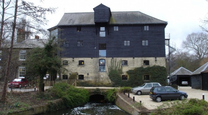
This site is owned by Natural Resources Wales (previously the Environment Agency Wales) and used as a salmon hatchery. There was keen interest from the fisheries team in harnessing the surplus flow of water in the former mill leat which now supplies the fish rearing tanks to offset the energy consumption at the site. As the site is often left unattended, it was important that a system was installed which could be relied upon to work with little supervision.

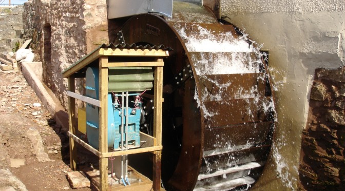
An overshot waterwheel was quickly identified as an appropriate solution which also made most sensible use of the existing infrastructure which was of course originally designed to incorporate a similar wheel.

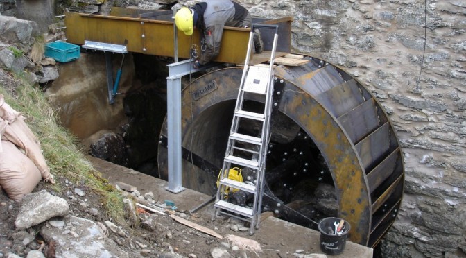
The scheme required planning permission, Environment Agency licensing and CDM regulations to be precisely followed during the installation. Nevertheless, the project was successfully commissioned and handed over to the Environment Agency staff within 6 months of the contract being signed with Pico Energy Ltd.

Currypool Mill

Hydromatch Consulting  Case Study 4 Site Name:  Currypool Mill
System type:  Overshot Waterwheel Power output: 6.5 kW 3 phase
Manufacturer: HydroWatt GmbH Typical Generation: 30 MWh p.a.
Client: Mr and Mrs Taylor Design Conditions: H = 3.20 m
Q = 0.35 m3/s
Location:  Cannington, Somerset Commissioned: November 2006
Project description:

A sawmill in a previous life, Currypool Mill was renovated by its new owners and converted into a family home. Options for power generation including a crossflow turbine and an overshot waterwheel were compared in terms of cost, power output and suitability for integration with the surrounding buildings. The simplicity, overall efficiency and lack of screening required favoured reinstatement of a waterwheel.

An old badly broken ‘Armfield’ turbine was removed and a new launder was installed along with an overshot wheel made from Corten steel, which was carefully dimensioned to fit the existing wheel pit.

The system operates without active flow regulation under normal generating conditions. During shutdown the flow is diverted behind the wheel via a trap door sluice in the launder. If the power is interrupted, the hydraulic circuit which normally holds the sluice shut, is de-energised and the door opens under its own weight. This provides a failsafe means of controlling the system.

The power produced is exported to the grid on a net metering basis. This enables the power to be consumed in the building if sufficient demand exists or otherwise exported. The system has been registered with OFGEM for the awarding of ROCs since 2006.

Lemsford Mill

Hydromatch Consulting Case Study 3 Site Name: Lemsford Mill
System type: ‘Zuppinger’ Waterwheel Power output: 15 kW
Manufacturer: HydroWatt GmbH Typical Generation: 65 MWh p.a.
Client: Ramblers Holiday Ltd Design Conditions: H = 2.00 m
Q = 1.35 m3/s
Location: Lemsford near Welywn
Garden City, Hertfordshire
Commissioned: August 2005

Lemsford waterwheel

Project description:

The listed former textile mill situated on the River Lea is the head office of Ramblers Holidays Ltd who undertook a program of significant refurbishment in order to provide a modern business premises for their 45 full-time staff prior to moving in in 2005. A feasibility study showed that hydropower could meet a significant part of the buildings energy consumption and compared to options using conventional turbines with a modern waterwheel. It was decided that a modern waterwheel was the most appropriate solution due to the considerable aesthetic benefit as well as cost-effectiveness compared to the turbine options. The new wheel dimensions are very similar to those of the original, which had disappeared and enabled a close fit into the existing wheel pit.

The wheel operation is regulated by a control system, which monitors the upstream water level. It adjusts the position of an overshot sluice gate along with a second relief channel sluice gate. An auxiliary power system enables the inlet sluice to close and water levels to be maintained upstream via the relief sluice in the event of disruption to mains power. The system is simple to operate and requires very limited maintenance.

The power produced is exported to the grid on a net metering basis. This means that the power is consumed in the building if sufficient demand exists and otherwise exported. The system has been registered with OFGEM for the awarding of ROCs since 2006. The building refurbishment with waterwheel was both regional and national winner of the British Council for Offices awards 2007 in the ‘small project’ category.

Thima

Pico Energy Ltd Case Study 2 Site Name: Thima
System type: Pump as Turbine Power output: 2.2 kW
Manufacturer: Kirloskar Typical Generation: 19 MWh p.a.
Client: Thima CEA Design Conditions: H = 20.00 m
Q = 0.28 m3/s
Location: Kerugoya, Kenya Commissioned: January 2002
Penstock installation Kenya
Project description:

This scheme was installed as part of a program implemented by The Micro Hydro Centre at Nottingham Trent University to demonstrate Pico Hydro technology in Sub Saharan Africa. The project was financed by the beneficiaries with some additional help from external organisations. The small generator is driven by a pump working in reverse as a turbine. It produces a constant 2.2 kW of AC electricity which provides a reliable electricity service to more than 110 households. This project won the Ashden Award’s ‘Overseas Project for Light’ in 2004.

The scheme is owned and managed by the beneficiaries. The community elected a committee to manage the collection of funds and to mobilise labour for installation. The same committee now manages the scheme operation and repairs, and tariff collection.

There are approximately 160 houses within the vicinity of the generator, the furthest of which is 900 metres from the turbine house. The locations of the houses were mapped with a GPS unit which saved considerable time as no accurate maps of the area existed. The shortest route to connect all of the houses to the generator was then worked out to ensure that all the consumers were connected. This helped to keep the connection costs for the consumers as low as possible. Insulated cables were used for all elements of the distribution system to maximise safety. Only small diameter cables were required as each house draws a small current. In addition to electrical insulation particular care was taken with regard to load management, lighting protection and earth fault protection to maximise consumer safety.